

диафрагмированные волноводные фильтры / 9aa43365-015b-4d2b-ace8-b8def9f0d29f
.pdfintegral K (k). The above mathematical expressions are computed by MATLAB code to evaluate the capacitance (" ) and inductance (2 ) values of CSRR. It is only suitable for a number of CSRR ring greater than one (N>1). If N=1 than " =L9:;;=0, so the above
equation only useful for N= 2, 3.
For, N=2 (Second ring CSRR) |
L = <+1=+ = 7.31 mm |
|
||
|
|
|
|
|
Hence, L9:;;= 6.7036 × 10$%5 (Henry) and C9:;;= 8.4330 × 10$A (Farad). Therefore, the |
||||
resonance frequency of second ring CSRR is = |
|
= 2.11 GHz. |
||
|
|
|||
!! !! |
||||
For, N=3 (Third ring CSRR) |
L = <B1=B = 5.31 mm |
|
|
|
|
|
|
|
|
Hence, L9:;;= 4.4067 × 10$%5 (Henry) and C9:;;= 5.9510 × 10$A (Farad). Therefore, the
resonance frequency of third ring CSRR is = = 3.10 GHz.
!! !!
From this quasi-static analysis, it is found that, second ring CSRR and third ring CSRR creates a resonance frequency of 2.11 GHz and 3.10 GHz, respectively. It matches with simulated resonance frequency at N=2 and N=3.
5. Results and discussion
Agilent Network Analyzer E8362B is used to measure the return loss characteristic of proposed antenna. The simulated return loss has compared with measured value as shown in Fig. 10. Results are listed in Table 3 numerically, both values identical with each other. The measured data exhibits a triple band resonance at 1.88 GHz, 2.94 GHz, and 5.5 GHz with -10 dB impedance bandwidth of 50 MHz (1.86−1.91 GHz), 90 MHz (2.89−2.98 GHz), and 1820 MHz (4.96−6.78 GHz), respectively, which is quite useful for GSM and WLAN applications. The radiation patterns of proposed antenna at 1.88 GHz, 2.94 GHz and 5.5 GHz are shown in Fig. 11(a)−(c). The results show that, a consistent dipole pattern exhibits in the elevation plane (E-plane) and omnidirectional pattern exhibits in the azimuthal plane (H- plane) for all operating bands.
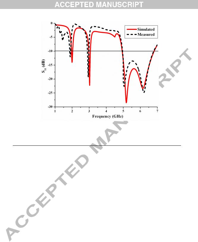
Fig. 10. Simulated and measured return loss characteristics of proposed antenna. Table 3 Comparison of simulated and measured values of the proposed antenna
Proposed antenna |
Resonant frequency |
Return loss (dB) |
Impedance |
|
(GHz) |
|
bandwidth (MHz) |
|
|
|
|
Simulated |
1.98 |
-14 |
70 |
|
3.03 |
-22 |
100 |
|
5.5 |
-17 |
1890 |
Measured |
1.88 |
-12 |
50 |
|
2.94 |
-19 |
90 |
|
5.5 |
-13 |
1820 |
|
|
|
|
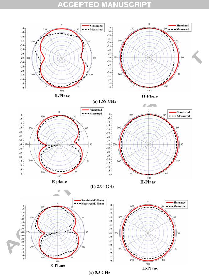
Fig. 11. Simulated and measured far field radiation patterns of the proposed antenna (a) 1.88
GHz, (b) 2.94 GHz, and (c) 5.5 GHz.
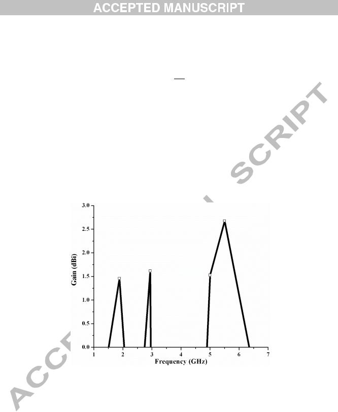
The gain transfer technique is used to calculate the antenna gain. Here, the horn antenna has utilized as reference antenna. The antenna gain is computed by [20]
CD = CE = F20 log % KALEM + 10 log % KOOPQ MR (2) Where CD= Transmitting antenna gain (dB), CE= Receiving antenna gain (dB),
r= Distance between transmitting and receiving antennas in terms of meters,
gD= Transmitted power (Watts), and gE= Received power (watts). The measured gain plot as a function of frequency is shown in Fig. 12. It is found that, the peak gain values of 1.46 dBi, 1.62 dBi and 2.68 dBi have been inferred for 1.88 GHz, 2.94 GHz and 5.5 GHz, respectively. 
Fig. 12. Measured gain plot of the proposed antenna
6. Parameter extraction of CSRR
CSRR shows the pass band characteristics with respect to CSRR geometrical parameters. The role of CSRR is to generate a new resonance frequency in order to achieve multiband at 1.98 GHz, 3.03 GHz and 5.5 GHz, respectively. This is verified by creating a pass band (S11)
of the proposed CSRR. For a detail analysis, the reflection coefficient (S11) and transmission
coefficient (S21) of the proposed CSRR are reconnoitered and compared by a classical
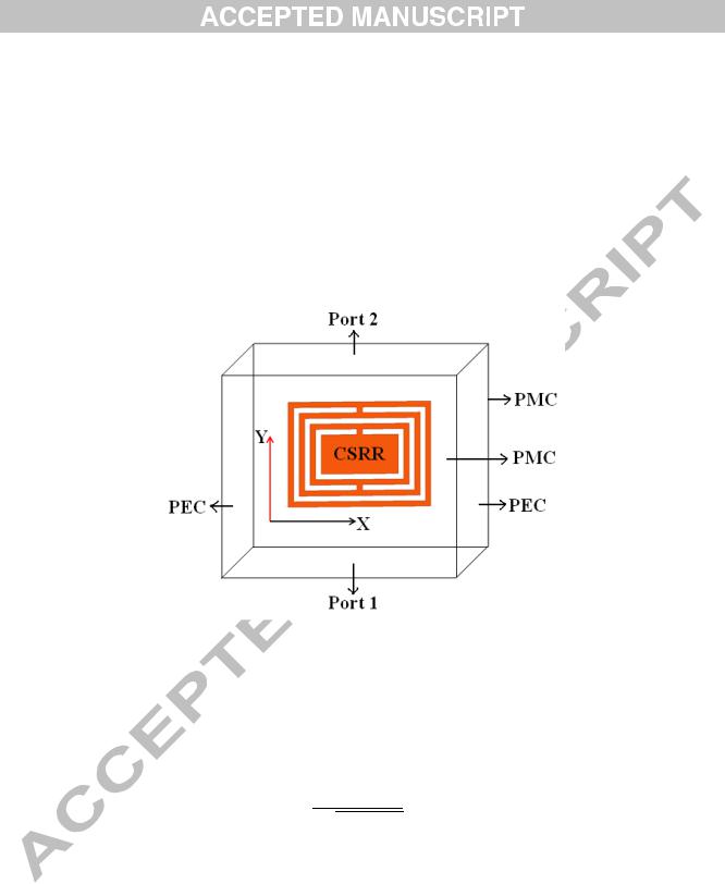
waveguide theory [21]. The schematic representation of the waveguide setup as shown in Fig. 13. Here, metamaterial element CSRR is placed within the waveguide of appropriate axis, which is enclosed by an electric field and magnetic field boundary conditions. CSRR creates an electric response by plane wave from input port (Port 1), and S-parameters (S11 and S21) are
retrieved from the output port (Port 2) of the waveguide.
Fig. 13. Schematic diagram of the waveguide setup for retrieving S-parameters.
The simulated S-parameters (S and S ) are graphically shown in Fig. 14. It is found
that three pass bands at 2.1 GHz, 3.1 GHz and 5.23 GHz, respectively. This pass band characteristics are responsible for generating a new resonance frequency. Here, 2.1 GHz and
3.1 GHz verify, to the relation = at N=2 and N=3, respectively. Real and
!! !!
imaginary parts of permittivity are depicted in Fig. 15. It is observed that the negative permittivity is inferred for frequencies at 2 GHz, 3 GHz and 5 GHz. This is understood that, negative permittivity occurs where the antenna has exposed a new frequency in the return loss characteristics. Hence, the proposed CSRR ring has contributed a new resonance frequency to attain multiband antenna.
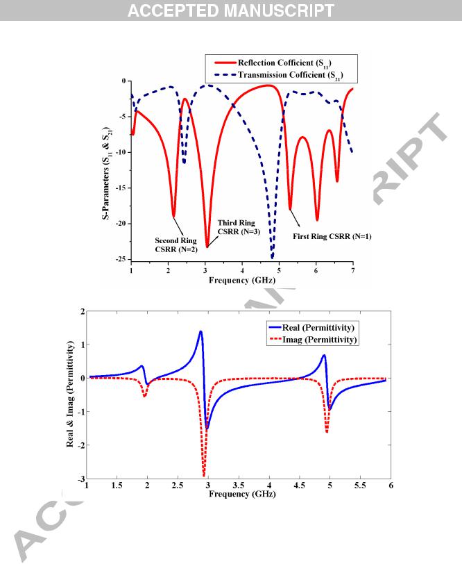
Fig. 14. Simulated S-parameters of proposed CSRR.
Fig. 15. Negative permittivity of the proposed CSRRs.
7. Conclusion
An offset fed CSRR loaded monopole antenna is proposed for GSM and WLAN applications, with a small size of 19.18 ×22.64 ×1.6 mm3. Number of CSRRs in the monopole antenna accounts for triple bands. The offset-fed microstrip line is used to obtain good impedance matching. The band characteristics of the proposed CSRR are acquired by a

classical waveguide theory method to confirm its metamaterial property at 2 GHz, 3 GHz and 5 GHz, which is possible to produce a new resonance frequency. The proposed antenna is fabricated and its radiation characteristics are measured. The simulated and measured results match with each other, and also agree with quasi-static equivalent circuit analysis. Due to small size, multiband characteristics and homogeneous radiation pattern, the proposed antenna is desirable for GSM (1.88 GHz) and WLAN (2.94/5.5 GHz GHz) applications.
References
[1]Christophe Caloz, Tatsuo Itoh. Electromagnetic metamaterials: Transmission line theory and microwave applications. New York: John Wiley & Sons, Inc.; 2006.
[2]Phani Kumar K. V, Karthikeyan S. S. Wideband three section branch line coupler using triple open complementary split ring resonator and open stubs. AEU Int J Electron C 2015;69(10):1412–16.
[3]Memarzadeh-Tehran Hamidreza, Abhari Ramesh , Niayesh Mohsen. A cavity-backed antenna loaded with complimentary split ring resonators. AEU Int J Electron C 2016;70 (7):928–35.
[4]He-Xiu Xu, Guang-Ming Wang, Chen-Xin Zhang, Qing Peng. Hilbert-shaped complementary single split ring resonator and low-pass filter with ultra-wide stopband, excellent selectivity and low insertion loss. AEU Int J Electron C 2011;65(11):901–05.
[5]Aidin Mehdipour, Tayeb A. Denidni, Abdel-Razik Sebak. Multi-band miniaturized antenna loaded by ZOR and CSRR metamaterial structures with monopolar radiation pattern. IEEE Trans Antennas Propag 2014;62(2):555–62.
[6]Minyeong Yoo, Sungjoon Lim. SRR and CSRR loaded ultra-wideband (UWB) antenna with tri-band notch capability. J Electromagnet Wave 2013;27(17):2190–97.

[7]Choudhury Anwesha, Maity Santanu. Design and fabrication of CSRR based tunable mechanically and electrically efficient band pass filter for K-band application. AEU Int J Electron C 2017;72:134–48.
[8]Mariem Aznabet, Otman El Mrabet, Jean Marie Floc’h, Francisco Falcone and M’hamed Drissi. A coplanar waveguide-fed printed antenna with complementary split ring resonator for wireless communication systems. Wave Random Complex 2015;25(1):43– 51.
[9]Pandeeswari R, Raghavan S. Microstrip antenna with complementary split ring resonator loaded ground plane for gain enhancement. Microwave Opt Technol Lett 2015;57(2):292–96.
[10]Boopathi Rani R, Pandey S.K. ELC metamaterial based CPW-fed printed dual-band antenna. Microwave Opt Technol Lett 2017;59(2):304–07.
[11]Liang Gong, King Yuk Chan, Rodica Ramer. Substrate Integrated Waveguide H-Plane horn antenna with improved front-to-back ratio and reduced side lobe level. IEEE Antennas Wireless Propag Lett 2016;15:1835–38.
[12]Liang Gong, King Yuk Chan, Rodica Ramer. Phase correction of the electric field for a dielectric loaded substrate integrated waveguide H-plane horn antenna. Microwave Opt Technol Lett 2017;59(3):584–88.
[13]Liang Gong, Yi Yang, King Y. Chan, and Rodica Ramer. RHCP pattern-reconfigurable spiral antenna biased with two DC signals. Microwave Opt Technol Lett 2014;56(7):1636–40.
[14]Liang Gong, Rodica Ramer, King Yuk Chan. Beam steering spiral antenna reconfigured by PIN diodes. Int J Microw Wirel Technol 2014;6(6):619–27.

[15]Basaran S.C, Sertel K. Multiband monopole antenna with complementary split ring resonators for WLAN and WiMAX applications, Electron Lett 2013;49(10):636–38.
[16]Saber Dakhil, Hatem Rmili, Jean-Marie Floch and Richard W. Ziolkowski. Printed multiband metamaterial inspired antenna. Microwave Opt Technol Lett 2016;58:1281–89.
[17]Boopathi Rani R, Pandey S.K. CSRR Inspired Conductor Backed CPW-Fed Monopole Antenna for Multiband Operation. Prog Electromagn Res C Pier C 2016;70:135–43.
[18]Bilotti F, Toscano A, Vegni L, Aydin K, Alice KB, for the design of metamaterials based on artificial Microwave Theory Technol 2007;55(12):2865–72.
Ozbay E. Equivalent circuit models magnetic inclusions. IEEE Trans
[19]Samson Daniel R, Pandeeswari R, Raghavan S. Multiband monopole antenna loaded with Complementary Split Ring Resonator and C-shaped slots. AEU Int J Electron C 2017;75:8–14.
[20]Rajkumar Rengasamy, Usha Kiran Kommuri. A compact metamaterial multiband antenna for WLAN/WiMAX/ITUband applications. AEU Int J Electron C 2016;70(5):599–04.
[21]Immaculate S, Singaravalu Raghavan. A compact dual band antenna with an ENG SRR cover for SAR reduction. Microw Opt Technol Lett 2015;57(3):741-47.