

диафрагмированные волноводные фильтры / 07949936-2a4f-4b53-aa3f-86eb30dac3f0
.pdfThis article was downloaded by: [University of Tennessee, Knoxville] On: 21 March 2013, At: 11:13
Publisher: Taylor & Francis
Informa Ltd Registered in England and Wales Registered Number: 1072954 Registered office: Mortimer House, 37-41 Mortimer Street, London W1T 3JH, UK
Journal of Electromagnetic Waves and Applications
Publication details, including instructions for authors and subscription information:
http://www.tandfonline.com/loi/tewa20
An Accurate Design of E-Septum Waveguide Filters with
Improved Stopband, Based on Mode Matching Method
M. Gharib a , E. Mehrshahi b & M. Tayarani c
aDepartment of Electrical Engineering, Shahid Beheshti University, Tehran, Iran
bDepartment of Electrical Engineering, Shahid Beheshti University, Tehran, Iran
cDepartment of Electrical Engineering, Iran University of Science & Technology, Tehran, Iran Version of record first published: 03 Apr 2012.
To cite this article: M. Gharib , E. Mehrshahi & M. Tayarani (2008): An Accurate Design of E-Septum Waveguide Filters with Improved Stopband, Based on Mode Matching Method, Journal of Electromagnetic Waves and Applications, 22:14-15, 2003-2013
To link to this article: http://dx.doi.org/10.1163/156939308787537991
PLEASE SCROLL DOWN FOR ARTICLE
Full terms and conditions of use: http://www.tandfonline.com/page/terms-and-conditions
This article may be used for research, teaching, and private study purposes. Any substantial or systematic reproduction, redistribution, reselling, loan, sub-licensing, systematic supply, or distribution in any form to anyone is expressly forbidden.
The publisher does not give any warranty express or implied or make any representation that the contents will be complete or accurate or up to date. The accuracy of any instructions, formulae, and drug doses should be independently verified with primary sources. The publisher shall not be liable for any loss, actions, claims, proceedings, demand, or costs or damages whatsoever or howsoever caused arising directly or indirectly in connection with or arising out of the use of this material.
Downloaded by [University of Tennessee, Knoxville] at 11:13 21 March 2013
J. of Electromagn. Waves and Appl., Vol. 22, 2003–2013, 2008
AN ACCURATE DESIGN OF E-SEPTUM WAVEGUIDE FILTERS WITH IMPROVED STOPBAND, BASED ON MODE MATCHING METHOD
M. Gharib and E. Mehrshahi
Department of Electrical Engineering
Shahid Beheshti University
Tehran, Iran
M. Tayarani
Department of Electrical Engineering
Iran University of Science & Technology
Tehran, Iran
Abstract—A computer-aided synthesis technique for E-septum bandpass filters with improved stopband and spurious mode rejection performance is developed. This design is based on field expansion into suitably normalized eigen-modes which yields directly the modal S - matrix. Higher order mode excitation and finite thickness of inserts are included in the calculations. The analysis results of proposed structure show the improvement of stopband performance and reduction of filter dimensions compared with conventional E-septum bandpass filter. The validity of the analysis results are confirmed by the HFSS. The computing time of our proposed method is decreased dramatically comparing with the HFSS.
1. INTRODUCTION
Conventional metal insert filters have drawn considerable attention over the past few years specially at millimeter-waves (Fig. 1) [1– 3]. These filters consist of metal strips inserted along the E -plane of a rectangular waveguide. The inserts are easily fabricated with photolithography method.
E-septum filters with all metal inserts have been originally suggested as low-cost, mass-producible and low-dissipation loss structures. However, these filters also su er from the spurious

Downloaded by [University of Tennessee, Knoxville] at 11:13 21 March 2013
2004 |
Gharib, Mehrshahi, and Tayarani |
Figure 1. Conventional E-septum filter with all metal insert.
passbands and which result in poor stopband performance specially, at wide band designs. The first reason is that, beyond the cuto frequency of the fundamental mode within the septum section which is nearly equal with the resonator section, the power is transported directly by propagating waves, which destroys filter behavior of the inductive strip-coupled resonators and show the genuine highpass behavior. The second reason is, due to the second resonant frequency (T E102) of cavity filters which appears almost at 1.5 times of dominant mode frequency.
Several solutions have been proposed recently to improve the second stopband of E-septum filters [4–10]. This paper present an accurate method for the conventional E-septum filter design procedure using a distributed low-pass prototype element derived by Rhodes [11]. The equivalent circuit of an E-septum inductive strip is used to obtain design parameters such as septum width and spacing.
In addition, an E-septum filter with the perturbed resonators is introduced. The new resonators have di erent second resonant frequencies. It is shown that this configuration can suppress the spurious passband of the filter. Higher-order mode-coupling e ects and the finite thickness of the metal insert are taken into account to make the computational results accurate.
2. PROPOSED CONFIGURATION
Based on the perturbation theory, we are using resonators with di erent second mode resonant frequencies while the fundamental resonant frequency is the same for all of them. Therefore, spurious mode rejection and improved stopband attenuation are resulted.
It is well known that the resonant frequency for waveguide cavities
Downloaded by [University of Tennessee, Knoxville] at 11:13 21 March 2013
Accurate design of E-septum waveguide filters |
2005 |
depend on the size. Based on the perturbation theory, the resonant frequency will be changed by the resonator volume variation. There is no field variation along the y axis for T Em0 modes, so T E101 mode is the dominant resonant mode. Therefore the next resonant mode is the
T E102 mode.
According to perturbation theory, the fractional change in the
resonant frequency can be written as follows [12]: |
|
|
|
||||||||||||||||
ω |
|
ω |
|
|
|
µ0 |
| |
H0 |
| |
2 |
− |
ε0 |
E0 |
| |
2 |
dV |
|
|
|
|
− |
|
0 |
= |
∆V |
|
|
|
| |
|
|
|
|
|
(1) |
||||
|
ω0 |
|
V0 µ0|H0|2 + ε0|E0|2 dV |
|
|
||||||||||||||
|
|
|
|
|
|
||||||||||||||
where V0 is the volume of the resonant cavity, |
|
|
are the |
||||||||||||||||
E0 |
and H0 |
||||||||||||||||||
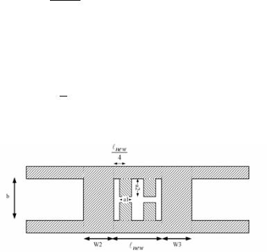
unperturbed electric and magnetic field, respectively. The change in the resonant frequency depends on the location of the perturbation in the resonant cavity. The maximum frequency shift at T E102 mode and minimum variation of T E101 mode is achieved by perturbing the cavities at 4 and 34 . At these points the electric field of T E102 mode is maximum. The slight frequency shift of the dominant mode is also compensated by reduction of the resonator length (Fig. 2) ( new < ).
Figure 2. Perturbed resonator structure.
3. NUMERICAL RESULTS
The E-septum filter design procedure is based on the mode matching method [13–15]. Once the dimensions of the filter have been determined, the frequency response of the overall filter (Fig. 3) at each frequency can be simulated by cascading the ABCD matrices of the resonators and the septum. All of the results presented in this paper

Downloaded by [University of Tennessee, Knoxville] at 11:13 21 March 2013
2006 |
Gharib, Mehrshahi, and Tayarani |
have been obtained by a computer program which takes into account the finite thickness of metallization and higher order modes.
Figure 3. Conventional E-septum filter structure.
Conventional metal insert filters in X-band and Ka-band have been designed with the CAD program. The specifications of these filters are given in Table 1. Figs. 4 to 7 show the calculated insertion loss and return loss of these filters without improvement.
Table 1. The specifications for designed filters.
Freq. |
Waveguide |
Septum |
Number of |
Mid-band |
3dB band |
band |
housing |
thickness |
Resonators(n) |
Freq.(GHz) |
width(MHz) |
|
a=22. 8 mm |
0.13 mm |
3 |
8.75 |
500 |
X-band |
b=10.16 mm |
||||
|
WR90 |
|
|
|
|
X-band |
a=22. 8 mm |
0.1 mm |
5 |
9 |
1000 |
b=10.16 mm |
|||||
|
WR90 |
|
|
|
|
|
a=5.69 mm |
0.2 mm |
4 |
39.5 |
400 |
Ka-band |
b=2.845 mm |
||||
|
WR22 |
|
|
|
|
X-band |
a=22. 8 mm |
0.1 mm |
7 |
9 |
1000 |
b=10.16 mm |
|||||
|
WR90 |
|
|
|
|
The combination of the mode matching and the generalized scattering matrix analysis of filter shows much less computation time in comparison with HFSS, which it is based on the finite element method (Table 3).
In order to demonstrate the performance of the new proposed filter, a 7 resonators X-band filter has been chosen as an example. The
Downloaded by [University of Tennessee, Knoxville] at 11:13 21 March 2013
Accurate design of E-septum waveguide filters |
2007 |
Table 2. The specifications for designed filters (continued).
W1 =Wn+1 |
W |
2 |
= W |
W |
= W |
- 1 |
W4 = Wn- 2 |
L1= Ln |
L2 = Ln -1 |
L3 = Ln - 2 |
L4 |
Max. passband |
|
|
n |
3 |
n |
|
|
|
(mm) |
(mm) |
ripple(dB) |
||
(mm) |
|
(mm) |
(mm) |
|
(mm) |
(mm) |
(mm) |
|||||
|
|
|
|
|
|
|
|
|
|
|
||
0.302 |
3.195 |
|
|
|
|
19.153 |
20.065 |
|
|
0.028 |
||
0.03 |
|
1.72 |
|
2.85 |
|
2.85 |
17.24 |
18.5 |
18.69 |
|
0.06 |
|
1.05 |
|
3.41 |
|
3.73 |
|
3.73 |
3.88 |
3.9 |
|
|
0.1 |
|
0.1 |
|
|
2 |
|
3.23 |
|
3.6 |
17.28 |
18.48 |
18.68 |
18.71 |
0.08 |
Table 3. The required time for the filter analysis.
Filter |
Freq. |
Freq. |
Number of |
∆S at |
Computation time of our |
Time for |
order |
sweep(GHz) |
step(MHz) |
modes |
HFSS |
method |
HFSS |
|
|
|
|
|
|
|
3 |
7-15 |
62.5 |
50 |
0.007 |
<2min |
4hour |
4 |
38.5-40.5 |
31.25 |
50 |
0.02 |
1:30min |
>6hour |
5 |
7-14 |
62.5 |
50 |
0.01 |
<4min |
>7hour |
7 |
7-14 |
62.5 |
50 |
0.02 |
<5min |
9hour |
Table 4. The dimensions of the designed filter resonators (in mm) with the same coupling widths of conventional filter.
L1 = L7 =16.5 |
a4 = a6 = 4.6 |
L2 = L6 =8 |
s1 = 3.125 |
L3 = L5 =18.68 |
s2 = 6.25 |
L4 = 8 |
s3 = s5 =1 |
a1 = a3 =a5 =2 |
s4 = s6 = 2 |
a2 = 1 |
b=10.16 |
filter structure is shown in Fig. 8. The dimensions of the designed filter resonators are given at Table 4.
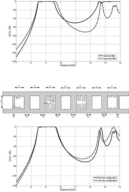
A comparison with an equivalent structure containing a standard E-septum bandpass filter is made in Fig. 9. The total length of a standard E-septum filter and proposed filter is 146 mm and 112 mm, respectively. A size reduction of more than 23% is achieved [16–23].
dependency of perturbed resonators arrangement.
This method is applied to 3 and 5 order X-band filters. The improvement of these filters in their stopband (at 11.5 GHz) is given at Table 5. The resonators arrangement is very important. Fig. 10 shows the other configuration of the proposed filter with di erent arrangement. The dimensions of the resonators are given at Table 6.

Downloaded by [University of Tennessee, Knoxville] at 11:13 21 March 2013
2008 |
Gharib, Mehrshahi, and Tayarani |
Figure 4. The 3-resonators X-band filter.
Figure 5. The 5-resonators X-band filter.
Table 5. Improvement in the second stopband of these filters.
Filter order |
Mode rejection@11.5GHz |
3 |
4dB |
5 |
19dB |
7 |
24dB |
Downloaded by [University of Tennessee, Knoxville] at 11:13 21 March 2013
Accurate design of E-septum waveguide filters |
2009 |
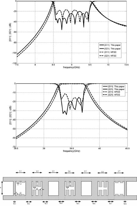
Figure 6. The 7-resonators X-band filter.
Figure 7. The 4-resonators Ka-band filter.
Figure 8. The 7 resonators X-band proposed filter structure.
Downloaded by [University of Tennessee, Knoxville] at 11:13 21 March 2013
2010 |
Gharib, Mehrshahi, and Tayarani |
Figure 9. A comparison between the standard E-septum filter and the proposed filter.
Figure 10. The other configuration of the proposed filter.
Downloaded by [University of Tennessee, Knoxville] at 11:13 21 March 2013
Accurate design of E-septum waveguide filters |
2011 |
Table 6. The dimensions of the designed filter resonators with new configuration (in mm) with the same coupling widths of conventional filter.
L1 |
= L7 =16.5 |
a4 = 4.6 |
L2 |
= L6 = 18.6 |
s1 = 3.125 |
L3 = L5 = 8 |
s2 = 6.25 |
|
|
L4 = 18.8 |
s3 = 1 |
a1 = a3 = 2 |
s4 = 2 |
|
|
a2 = 1 |
b =10.16 |
It is clear that the first configuration has higher stopband attenuation, which shows the dependency of perturbed resonators arrangement.
4. CONCLUSION
A computer-aided design technique for the accurate design of E-septum filters has been developed, which significantly reduces the required time for design and analysis. Higher-order mode-coupling e ects and the finite thickness of the metal insert are taken into account. This paper proposes a new configuration which can suppress the spurious passband of the bandpass filter and modifies the stopband sharpness. This configuration also reduces the physical length. Main feature of new structure is the use of the metal mounted conventional rectangular waveguide housing. The structure is simple and compatible with the E-septum manufacturing.
REFERENCES
1.Shih, Y. C., “Design of waveguide E -plane filters with all metal insert,” IEEE Trans. Microwave Theory Tech., Vol. 32, 695–704, 1984.
2.Konishi, Y. and K. Uenakada, “The design of a bandpass filter with inductive strip-planar circuit mounted in waveguide,” IEEE Trans. Microwave Theory Tech., Vol. 22, 869–873, 1974.
3.Tajima, Y. and Y. Sawayama, “Design and analysis of a waveguide sandwich microwave filter,” IEEE Trans. Microwave Theory Tech., Vol. 22, 839–841, 1974.