

диафрагмированные волноводные фильтры / 17107668-50e1-4ad7-86c6-13ca9e53650a
.pdfProceedings of the 37th European Microwave Conference
Novel Millimetre Wave Metawaveguide
Resonators and Filters
Suntheralingam Niranchanan, Alexander Shelkovnikov and Djuradj Budimir
Wireless Communications Research Group, Department of Electronic Systems University of Westminster,
London, W1W 6UW, United Kingdom
Abstract— This paper investigates novel class of E-plane metawaveguide resonator and filter structures for use at X-band, mm-wave, submm-wave and terahertz frequencies. It aims to show that this type of resonator can be easily realized with a single metalo-dielectric insert within rectangular waveguide. The simulated results for air-filled metal pipe half-wavelength rectangular waveguide resonator and resonator structure using S-shaped SRR at 9.45 GHz, 57 GHz and 65 GHz are presented. Experimental results at 9.45 GHz validate the argument for the other cases.
I. INTRODUCTION
Modern ways of research and development in telecommunications today are led by customer demands for mobile, robust and convenient information services at any place and any time. As a result, at microwaves, suitable for mass production, low-cost passive devices are widely required in order to build the essential components of microwave communication systems. High quality resonators are essential for the most of microwave circuits and systems. At microwave frequencies, the quality factor (Q factor) of metal transmission line resonant circuits is known to be proportional to their volume. Consequently, rectangular waveguide resonators are employed in order to achieve higher Q. However, the difficulty of integration and high cost of conventional rectangular waveguides makes it improper to utilize them for modern applications. The classical rectangular waveguide theory, as a result, is extensively employed in order to build the novel waveguide circuits [1]-[3], viable to meet the actual requirements.
Rectangular waveguides have been a sustainable solution over the past few decades, used to design robust, low loss and high power circuits at microwave and millimeter-wave frequencies. In the resonator structures, which are viable to meet requirements of the modern technology [1], reduction of the physical size has become one of the primary goals. Recently proposed concepts of left-handed medium (LHM) have become the subject of extensive investigations due their capability to provide novel unconventional properties to different propagation media [2]-[4]. This approach makes use of the left-handed medium created by a novel type of resonance elements, Split Ring Resonators (SRRs), in combination with the thin metal wireline [4]. These are printed on the dielectric slab, which is then inserted into the plane of symmetry of the rectangular waveguide. These structures are able to alter the electromagnetic boundary
conditions of the surface and prohibit propagation of signal in a certain frequency band. Thus, the traditional miniaturization techniques, which commonly employ dielectric-filled waveguides with standard dimensions bound to the wavelength (Ȝ), may be enhanced to achieve more compact high-performance waveguide components.
In recent years there has been a strong interest worldwide in developing advanced periodic structures for microwave, mm-wave and optical applications. We have investigated several waveguide and quasi-planar periodic structures and demonstrated their applications in high-Q resonators. One particular type of structure, the resonator with S-shaped, has been developed in our laboratory. High quality resonator elements are key to the function of most microwave circuits and systems.. Waveguide resonators are often employed to increase Q. The split block housing and all metal E-plane insert technology is a cost efficient way of realizing half wavelength waveguide resonators [1]. In such a configuration, all metal septa placed at the E-plane of a waveguide at distance roughly half a wavelength apart act as reflective discontinuities, required for the formation of the resonant standing wave, while allowing controlled coupling of electromagnetic waves to and from the resonator. For an E- plane all metal septum discontinuity, the reflectivity is increased with the length of the septum, and therefore resonators with longer septa exhibit higher Q-factors. This however is at the expense of the physical dimension of the resonator. SRRs of various shapes have been a favourite topic of researchers and are currently enjoying renewed interest in the microwave field for their applications in the microwave and millimeter-wave regime [5,6,7,8]. In particular, it has been reported that split ring resonator loaded waveguides can be employed to reduce the size of microwave components [9]. This is due to the slow-wave effect; the phase velocity of the wave propagating in a periodically loaded line is reduced realtive to a comparable uniform line, such that the guided wavlength is reduced.
This paper therefore proposes for replacement of the conventional section of rectangular waveguide in the resonators of E-plane filters with a S- shaped SRR resonator structure, consisting of a periodic cascade of metal septa and two S-shaped SRR units. It maintains the low-cost and massproducible characteristics of split-block all-metal insert E- plane technology.
978-2-87487-001-9 ♥ 2007 EuMA |
913 |
October 2007, Munich Germany |
II. PROPOSED STRUCTURES
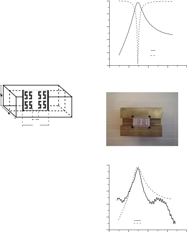
The proposed metawaveguide S-shaped SRR resonator is shown in Fig.1. The proposed resonator structure is constructed of the transmission line loaded with the metaldielectric slab, which conveniently facilitates S-shaped split ring resonator with the metal septa. The S-shaped SRR are presented on both sides of the dielectric block and is characterised by the following parameters. The dielectric which has relative dielectric permittivity of 2.2, thickness of 1.0 mm supports this S-shaped SRR and metallisation thickness of 0.017 mm. Standard rectangular waveguides of WG-16 (a = 22.86 mm, b = 10.16 mm) and WG-25 (a = 3.759 mm, b=1.88 mm) have been used as housing to fit the 1.0 mm thick dielectric slab.
|
0.00 |
|
|
|
|
|
-5.00 |
|
|
|
|
(dB) |
-10.00 |
|
|
|
|
S-parameters |
|
|
|
|
|
-15.00 |
|
|
|
|
|
|
|
|
|
|
|
|
-20.00 |
|
|
S21 |
|
|
|
|
|
S11 |
|
|
-25.00 |
|
|
|
|
|
8.00 |
9.00 |
10.00 |
11.00 |
12.00 |
Frequency (GHz)
Fig. 2. Simulated S-parameters of the S-shaped SRR-loaded resonator at 9.45 GHz
d |
lres |
Fig.1. Configuration of the proposed E- Plane metawaveguide resonator
III. SIMULATION AND MEASURED RESULTS
In order to illustrate the feasibility of the proposed S- shaped SRR-loaded waveguide resonator structure, it has been fabricated and tested in our lab at 9.45 GHz, X-band. Standard rectangular waveguide (WG-16: a = 22.86 mm, b = 10.16 mm) has been used as a housing to fit a 1.0 mm-thick dielectric slab. In this case d = 1.5 mm and lres = 12 mm. The simulated S- parameters of this proposed E-plane resonator using S-shaped SRR at center frequency of 9.45 GHz are shown in Fig.2. Fig.3. shows the photograph of the fabricated S-shaped SRR loaded metawaveguide resonator. Simulated and measured insertion losses of the SRR-loaded metawaveguide resonator at this frequency are shown in Fig.4. The measured response demonstrates a very good agreement with the simulation. The response of the fabricated resonator was measured with Agilent PNA (E8361A) network analyzer.
Fig. 3. Photograph of a fabricated S-shaped SRR Resonator
|
0.00 |
|
-5.00 |
(dB) |
-10.00 |
|
|
21 |
|
S |
|
|
-15.00 |
|
-20.00 |
|
measured |
|
simulated |
|
-25.00 |
8.00 |
9.00 |
10.00 |
11.00 |
12.00 |
Frequency (GHz)
Fig.4. Simulated and measured insertion loss of the SRR-loaded waveguide resonator at 9.45 GHz
914
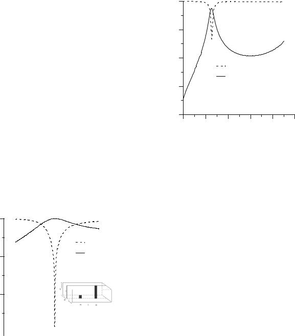
Fig.5. shows the simulated S-parameters of the conventional half-wavelength waveguide resonator at 57 GHz. The simulated return loss and insertion loss of the proposed resonator at 57 GHz are shown in Fig.6. In order to validate the argument made the resonators have been designed and those loaded quality factor are compared with conventional half-wavelength E-plane waveguide resonator of the same resonant frequency.
The electromagnetic analysis of the conventional E-plane waveguide resonator structure is conveniently based on the mode matching method [11]. Mode matching with 60 modes has been used for the simulation of the conventional E-plane waveguide resonator case while finete element method (HFSSTM) [12] for the proposed metawaveguide S-shaped SRR resonator. Both methods are well-established and therefore expressions are not given here. In order to derive a design procedure for the proposed type of resonators, the propagation characteristics of the slow wave, such as the guided wavelength or phase velocity, need to be determined. These in turn are determined by geometrical parameters, namely the gaps and the lengths. The gaps can be chosen arbitrarily. The periodicity lengths, together with the chosen gaps will effectively determine the wavelength; this in term should determine the length lres. Dimensions for the two resonators at 57 GHz are given in Table 1.
|
0.00 |
|
(dB) |
|
S11 |
parameters-S |
-20.00 |
S21 |
|
-40.00
-60.00 |
|
|
|
|
|
|
|
|
|
|
|
|
|
|
|
|
|
|
|
|
|
|
48.00 |
52.00 |
56.00 |
60.00 |
64.00 |
68.00 |
|||||||||||||||||
|
|
|
|
|
|
|
|
Frequency (GHz) |
|
|
|
|
|
|
|
|
||||||
Fig.5. Simulated S-parameters of the conventional E-plane waveguide resonator at 57 GHz.
|
0.00 |
|
|
|
|
|
(dB) |
-10.00 |
|
|
|
|
|
S-parameters |
|
|
|
|
|
|
-20.00 |
|
|
|
|
|
|
|
|
|
|
|
|
|
|
|
|
S11 |
|
|
|
|
|
|
S21 |
|
|
|
|
-30.00 |
|
|
|
|
|
|
-40.00 |
|
|
|
|
|
|
52.00 |
56.00 |
60.00 |
64.00 |
68.00 |
72.00 |
|
|
|
Frequency (GHz) |
|
|
|
Fig.6. Simulated S-parameters of the S-shaped SRR-loaded resonator at 57 GHz
TABLE I
DIMENSIONS AND Q-FACTORS OF THE RESONATORS
|
Conventional |
Proposed meta- |
|
E-plane |
waveguide |
|
resonator at |
resonator at 57 |
|
57 GHz |
GHz |
Inside waveguide |
|
|
dimensions in mm |
3.759 x 1.880 |
3.759 x 1.880 |
(WG-25) |
|
|
Metallization |
0.10 |
0.0017 |
thickness in mm |
|
|
Dielectric thickness |
0.00 |
1.0 |
in mm |
|
|
Length of the metal |
0.25 |
- |
septum in mm |
|
|
Distance between |
- |
2.7 |
two S-shaped SRR |
|
|
units (d) in mm |
|
|
Distance between |
2.6 |
- |
two metal septa |
|
|
Resonator length in |
3.1 |
4.8 |
mm |
|
|
Loaded Q-factor |
31.80 |
63.44 |
( QL) |
|
|
Unloaded Q-factor |
- |
197.45 |
(QU) |
|
|
From the S-parameter responses shown in Fig.5. and Fig.6., the loaded Q (QL) of the resonators can be directly calculated as the ratio of the centre frequency fo (fo= 57 GHz for both resonators) with the 3dB bandwidth ('f3dB= 1.8 GHz, 0.83 GHz for the proposed S-shaped SRR and conventional E- plane rectangular waveguide resonator respectively). Therefore, we calculated that the proposed S-shaped SRR resonator has QL=63.44. The conventional E-plane waveguide
915
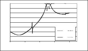
resonator at the same resonant frequency has QL=31.80. As we can see in Table 1, QL factor of novel resonator is 100% higher. Fig.7. shows the simulated S-parameters of the metawaveguide bandpass filter at 65 GHz.
shown that it is 100% higher than the conventional E-plane resonator.
REFERENCES
|
|
|
|
|
|
[1] |
|
0 |
|
|
|
|
[2] |
|
|
|
|
|
|
|
|
-10 |
|
|
|
|
[3] |
S-parameters(dB) |
-20 |
|
|
|
|
|
|
|
|
|
|
||
-30 |
|
|
|
|
|
|
-40 |
|
|
|
|
[4] |
|
-50 |
|
|
|
|
||
|
|
|
|
|
||
-60 |
|
|
S12 |
S11 |
[5] |
|
|
|
|
|
|||
|
-70 |
|
|
|
|
|
|
|
|
S21 |
S22 |
|
|
|
-80 |
|
|
|
||
|
|
|
|
|
|
|
|
40 |
50 |
60 |
70 |
80 |
[6] |
|
|
|
Frequency(GHz) |
|
||
|
|
|
|
|
||
Fig.7. Simulated S-parameters of the bandpass filter |
[7] |
IV.CONCLUSION |
|
A novel class of E-Plane metawaveguide high-Q resonator |
[8] |
and filter structures for X-band, mm-wave, submm-wave and |
|
terahertz applications has been proposed. These can be easily |
|
realized with a single metal insert within a rectangular |
[9] |
waveguide. At 9.45 GHz the fabricated SRR shows that it is |
|
easily realizable and the simulated and measured insertion loss |
[10] |
of the SRR-loaded waveguide resonator demonstrates a good |
|
agreement. This validates the argument for the other cases. At |
|
57 GHz the QL factor of the novel resonator is compared and |
[11] |
D.Budimir, "Generalized Filter Design by Computer Optimization", ISBN 0-89006-579-9, Atrtech House Books, 1998.
H. Contopanagos, N. G. Alexopoulos, and E. Yablonvitch, “High-Q Ractangular Cavities and Waveguide Filters Using Periodic MetaloDielectric Slabs”, IEEE MTT-S Digest, pp 1539-1542, l998.
T. Yoneyama, and S.Nishida, “Nonradiative Dielectric Waveguide for Millimeter-wave Integrated Circuits”, IEEE Transactions on Microwave Theory and Techniques, Vol. MTT-29, No.11, pp 11881192, Nov. 1981
G. J. Cunningham, P. A. Blenkinsop, and J. H. Palmer, “Microstrip End-coupled Filter Design at mm-wave Frequencies “European Microwave Conference, pp. 1210-1213 Sept l989.
V.G. Veselago, “The Electrodynamics of Substances with Simultaneously Negative Values of İ and μ,” Soviet Phys. Uspekhi, vol. 10, no. 4, pp. 509-514, Jan.-Feb. 1968
J.B. Pendry, A.J. Holden, D.J. Robbins, and W.J. Stewart, “Magnetism From Conductors and Enhanced Nonlinear Phenomena,” IEEE Trans. Microwave Theory & Tech., vol. 47, no. 11, pp. 2075-2084, November 1999
D. R. Smith, W. J. Padilla, D. C. Vier, S. C. NematNasser, and S. Schultz, “Composite Medium with Simultaneously Negative Permeability and Permittivity,” Phys. Rev. Lett., vol. 84, pp. 41844187, May 2000
Yan Li, L. Ran, H. Chen, J. Huangfu, X. Zhang, K. Chen, T. M. Grzegorczyk, and J. A. Kong, “Experimental Realization of a OneDimensional LHM-RHM Resonator,” IEEE Trans. Microwave Theory & Tech., vol. 53, no. 4, pp. 1522-1526, April 2005.
A. Shelkovnikov, N. Suntheralingam, and D. Budimir, "Novel SRR Loaded Waveguide Bandstop Filters," IEEE AP-S/URSI Int. Symp., Albuquerque, USA, July 2006
D. Budimir, "EPFIL-Waveguide E-plane Filter |
Design", |
Software and User Manual, ISBN 1-58053-083-4, Artech |
House |
Books, 1999. |
|
Ansoft HFSS, Ansoft Technologies, 2005. |
|
916